
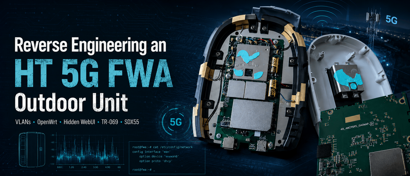
Introduction
This investigation started with an outdoor 5G FWA unit that was never really meant to be touched by the customer.
The normal HT installation consists of two devices. An outdoor unit handles the mobile connection, while an indoor Arcadyan router provides Ethernet, Wi-Fi, DHCP, and the interface the customer is expected to use.
From the outside, the outdoor unit looks like little more than a directional modem in a weatherproof enclosure. A single Ethernet cable carries power and data to it, and the indoor router takes care of everything else.
The sticker on the outdoor unit suggested that the situation was more complicated. In addition to the model information and Ethernet MAC address, it contained a Bluetooth ID, a username, and a password. That immediately raised several questions.
Why did an outdoor modem need Bluetooth credentials?
Did it have its own WebUI?
Could the Arcadyan router be replaced with OpenWrt?
Was the Ethernet connection carrying more than one logical network?
Did the unit contain remote-management services that were hidden from the customer interface?
And, most importantly, what was actually running inside it?
What began as an attempt to locate a WebUI eventually turned into a broader analysis of the entire platform. I mapped four active VLANs, replaced the Arcadyan router with OpenWrt, found hidden engineering pages, accessed detailed LTE and 5G diagnostics, disabled TR-069 through a page omitted from the normal navigation, collected a system archive, identified persistent SSH and Bluetooth services, and opened the enclosure to inspect the hardware and cooling design.
The work also had a practical result. At the beginning of the investigation, the connection was delivering roughly 90 Mbps. By the end, I was seeing speeds of approximately 500 Mbps.
I am intentionally not documenting the specific service-side change associated with that increase. The purpose of this article is to document the research process, the network architecture, the WebUI, the hidden diagnostics, the system internals, and the hardware – not to publish a method for changing an operator-imposed service profile.
1. The original installation
The original topology was straightforward:
Outdoor 5G FWA unit
        │
        │ Ethernet and PoE
        ▼
Arcadyan indoor router
        │
        ▼
Local network
The Arcadyan was the only device exposed to the customer in a meaningful way. Its interface provided all of the expected home-router functions, while the outdoor unit remained almost completely invisible.
The first useful information came from the Arcadyan status page.
It showed:
WAN protocol: DHCP
PPPoE status: disconnected
WAN address: private 10.x.x.x address
This was an important clue.
The indoor router was not authenticating with PPPoE. It was receiving its WAN configuration through DHCP from a service presented by the outdoor unit.
That meant there was a reasonable chance that another router could replace the Arcadyan, provided it used the same Ethernet configuration.
The problem was that connecting OpenWrt directly to the outdoor unit did not initially produce a working connection.
Something was missing.
2. Following the routing path
Before changing anything, I checked the route from a computer behind the Arcadyan.
The first few hops looked similar to this:
1    192.168.1.1
2    192.168.6.1
3    172.30.x.x
4    172.30.x.x
The obvious assumption was that 192.168.6.1 belonged to the outdoor unit and might expose its management interface.
That turned out to be the wrong lead.
The address was part of the forwarding path, but browsing to it did not reveal a useful interface. It was not the local management address I was looking for.
This was the first indication that the outdoor unit did not present all of its functions on a single ordinary Ethernet network.
The customer traffic and the management traffic were likely separated.
3. Replacing the Arcadyan with OpenWrt
I disconnected the Arcadyan and connected the outdoor unit directly to an OpenWrt router.
With the OpenWrt WAN interface configured as an ordinary, untagged DHCP client, it did not receive a usable internet connection.
That strongly suggested that the Arcadyan was tagging its WAN traffic, even though its normal status interface did not show the relevant VLAN configuration.
I started testing VLANs on the OpenWrt WAN port.
The first significant response came from VLAN 104.
OpenWrt received an address similar to:
Address: 192.168.4.11
Gateway: 192.168.4.1
This initially looked promising. The outdoor unit was clearly responding, DHCP was working, and the gateway replied to ping.
However, there was no internet access.
That meant VLAN 104 was valid, but it was not the customer internet handoff.
I had found a management network.
4. Discovering the active VLANs
Rather than guessing VLANs one at a time, I used OpenWrt to test a range of likely VLAN IDs.
The method was simple:
- Create a temporary VLAN interface on the physical WAN device.
- Bring it up.
- run
udhcpcon it. - Record any offered address.
- Remove the interface.
- Move to the next VLAN.
My first version of the script used the retry and timeout parameters which were built into udhcpc, meaning no external packages were needed.
The scan found four active VLANs:
VLAN 100 → 10.138.x.x
VLAN 101 → 10.43.x.x
VLAN 103 → 10.230.x.x
VLAN 104 → 192.168.4.x
Only VLAN 100 provided normal internet access.
The working OpenWrt WAN configuration was therefore:
Device: wan.100
Protocol: DHCP client
Firewall zone: wan
Once that was configured, OpenWrt could replace the Arcadyan as the customer router.
VLAN 104 remained useful as a separate management interface, but it had to be prevented from installing a default route or taking over DNS.
The practical arrangement became:
VLAN 100 → internet service
VLAN 104 → local management
VLANs 101 and 103 provided addresses from other private ranges, but they did not behave as ordinary customer internet connections.
Their exact role was still unknown at this point.
5. Locating the outdoor unit’s WebUI
With VLAN 104 active, 192.168.4.1 responded to ping.
Opening it over ordinary HTTP did not work, so I scanned the host.
The relevant result was:
53/tcp  open
443/tcp open
The management interface was HTTPS-only:
https://192.168.4.1
The credentials printed on the sticker worked.
The interface identified the unit as an outdoor FWA device connected to HT HR over 5G. It reported the APN as fwa.odu and displayed the software, modem, and hardware versions.
Nmap identified the HTTPS server as:
lighttpd 1.4.61
The TLS certificate was a self-signed WNC certificate, and the server supported TLS 1.2 and TLS 1.3.
The exposed management services were limited:
TCP 443      HTTPS WebUI
TCP/UDP 53   DNS
UDP 67/68    DHCP-related services
SNMP, UPnP, mDNS, and local NTP were not exposed during testing.
The visible WebUI contained ordinary router functions such as DHCP settings, firewall controls, URL filtering, DoS protection, NAT settings, and LED controls.
It did not show an Engineering Mode, TR-069 controls, SSH configuration, or Bluetooth settings.
6. The first attempt to inspect the frontend
To understand the WebUI, I began downloading its JavaScript.
The main page referenced files such as:
w_common.js
w_home.js
w_settings.js
w_system.js
w_firewall.js
w_update.js
w_login.js
The first download appeared to succeed, but the files were far too small to contain the frontend code.
They were actually 403 Forbidden responses saved with .js filenames.
The WebUI allowed the browser to load those resources as part of an authenticated session, but direct requests without the expected context were rejected.
The workaround was to send the requests with the current authenticated session cookie.
Once the files were downloaded through the authenticated session, they contained the actual frontend code.
This was the first important WebUI workaround. The files were not encrypted, obfuscated beyond recognition, or removed from the firmware. Access was only being restricted by simple session and request-header checks.
7. Understanding the CGI backend
The JavaScript showed that the WebUI does not use a conventional REST API.
Almost every operation is sent to one endpoint:
/cgi-bin/gui.cgi
A typical request looks like:
{
  "action": "get_wwan_ipv4_network_connection_time",
  "args": {},
  "token": "SESSION_TOKEN"
}
The response uses the action name as its main object:
{
  "get_wwan_ipv4_network_connection_time": {
    "errno": 0,
    "errmsg": "",
    "connection_time": "00:08:11:54"
  }
}
The frontend contains helper functions such as:
SendJsonAction()
SendJsonActionNoBlockUI()
SendJsonActionLogin()
SendJsonActionLoginNoBlockUI()
After login, the browser obtains a CGI token and adds it to subsequent requests.
Once this model was understood, the WebUI became much easier to analyze. Instead of searching for separate REST endpoints, I could search the JavaScript for action names such as:
get_tr069_config
get_wwan_rf_band_info
get_wwan_lte_ca_info
get_lan_bridge_mode_config
get_wwan_mpdn_settings
The frontend code also revealed page paths that did not appear in the normal navigation.
8. Finding the hidden engineering pages
Several engineering-related page fragments were present in the WebUI:
/system/system_eng_general.html
/system/system_eng_lte_ca.html
/system/system_eng_rf_band.html
/system/system_eng_log2device.html
/system/system_eng_log_collector.html
/system/system_device_tr069.html
Loading one of these URLs directly only returned the corresponding HTML fragment. The actual WebUI is built as a single application shell, and these fragments depend on the already-running frontend environment.
The correct method was to remain on the authenticated main page and use the WebUI’s own loader from the browser console.
For example:
loadHTML('/system/system_device_tr069.html');
The same approach worked for the radio and logging pages:
loadHTML('/system/system_eng_rf_band.html');
loadHTML('/system/system_eng_lte_ca.html');
loadHTML('/system/system_eng_log_collector.html');
This was not a matter of revealing a hidden navigation menu. I was loading specific hidden pages through the same internal mechanism used by the visible WebUI sections.
That distinction matters because the functionality depended on the main application context. The loader inserted the fragment into the active interface and invoked the matching JavaScript initialization function.
Once loaded that way, the hidden pages became functional.
9. The hidden TR-069 configuration page
The most significant hidden page was:
/system/system_device_tr069.html
It exposed the following settings:
TR-069 enable
ACS URL
ACS username
ACS password
Connection request username
Connection request password
Connection request port
Periodic inform enable
Periodic inform interval
Periodic inform time
The associated JavaScript called:
get_tr069_config
set_tr069_config
The configuration showed a private ACS endpoint on an HT network, using port 7023 and a CWMP management path.
The connection-request port was: 8547
The ACS and connection-request usernames were device-specific identifiers. Those values, along with the stored passwords, are not reproduced here.
I disabled TR-069 through this hidden page, rebooted the outdoor unit, and collected another system dump.
The setting remained disabled after reboot:
TR069_enable = 0
The stored ACS information was still present, but the primary enable flag remained off.
This proved that the hidden page was connected to the persistent device configuration. It was not an abandoned frontend mock-up or a page left behind without a backend.
10. What a technician’s Bluetooth access revealed
A later technician visit added an important real-world observation.
The technician used Bluetooth to establish access to the outdoor unit’s WebUI. This explains why the sticker contains a Bluetooth ID even though the device is not normally available as a conventional Bluetooth peripheral from a phone or laptop.
Bluetooth appears to provide a service or provisioning path to the same management interface rather than an unrestricted administrative shell.
The technician reached the login interface but could not authenticate because I had changed the WebUI password.
This is a useful observation for several reasons.
First, the technician’s Bluetooth workflow did not bypass the configured WebUI credentials. Changing the password affected the technician’s access as well.
Second, the tool or workflow used during that visit did not provide an obvious backdoor into the interface. It did not automatically authenticate with a hidden account, and it did not place the technician directly into an unrestricted engineering interface.
Third, the technician did not appear to have direct access to hidden pages such as the TR-069 configuration page.
This does not mathematically prove that no separate operator-side access mechanism exists. The system clearly contains TR-069 components, a running SSH daemon, provider-facing cellular interfaces, and firewall rules intended for controlled remote management.
What the visit does demonstrate is narrower and more concrete:
In the workflow I observed, Bluetooth was used to reach the normal WebUI, and the technician was still subject to the password I had configured.
That makes Bluetooth look more like a local transport or discovery mechanism than a privileged bypass.
It also makes the running bt_uartd process found later in the system dump more meaningful.
11. LTE and 5G diagnostics
The hidden radio pages exposed considerably more information than the normal status screen.
The LTE side showed:
PLMN: 21901
Band: 3
Channel: 1300
Bandwidth: 20 MHz
PCI: 112
ENDC available: true
The LTE connection was acting as the anchor for an NSA 5G connection.
The NR page showed:
Band: n78
Channel: 634080
Bandwidth: 100 MHz
PCI: 514
The four receive-chain RSRP values were approximately between -62 and -69 dBm, while the reported SSB-SINR was around 33 dB.
Those are strong 5G radio conditions.
The page also exposed values such as:
DL rank: 4
UL rank indicator: 4
DL modulation
CQI
SSB beam ID
uplink transmit power
neighbouring LTE and NR cells
This information helped put the speed tests into context.
At the beginning of the investigation, I was seeing approximately 90 Mbps. After the unit had been better understood and the final configuration was in place, speeds reached approximately 500 Mbps.
The exact service-profile modification associated with that increase is outside the scope of this article. However, the diagnostics were still valuable because they showed that the radio link itself was capable of much more than the initial result suggested.
The NR signal was not the obvious limiting factor.
The hidden pages also made it possible to distinguish between several possible causes of inconsistent performance:
- LTE anchor quality;
- NSA ENDC state;
- NR n78 signal quality;
- cell congestion;
- modulation and rank at the time of the test;
- router forwarding performance;
- differences between speed-test servers.
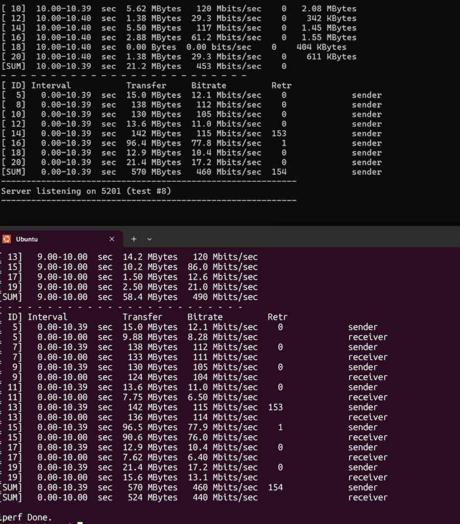
During the process, one test through OpenWrt produced only around 98 Mbps while another test later reached several hundred megabits without a corresponding physical link change.
I verified that the OpenWrt WAN and LAN ports were all negotiating at 1 Gbps full duplex. That ruled out a 100 Mbps Ethernet link as the explanation.
The mobile connection itself was clearly fluctuating, and different test services also produced significantly different results.

12. Making the hidden Log Collector usable
The Log Collector was discovered after the hidden page-loading mechanism was understood.
The relevant page was:
/system/system_eng_log_collector.html
Loading it through the WebUI shell made the log-generation and download workflow available:
loadHTML('/system/system_eng_log_collector.html');
The frontend used actions including:
log_collector_cmd
log_collector_download
event_log_collector_download
The generated archive contained much more than a conventional customer-support log.
It included:
- process listings;
- network-interface state;
- routing information;
- iptables rules;
- DHCP configurations;
- DNS configuration;
- lighttpd configuration;
- APN and MPDN settings;
- TR-069 configuration and logs;
- system and kernel logs;
- filesystem information;
- partition information;
- Qualcomm modem-interface state;
- startup and service information.
This archive changed the investigation from WebUI analysis into system analysis.
13. Identifying the platform
The dump identified the device as a Qualcomm SDX55/SDXPRAIRIE-class embedded platform.
The system ran:
Linux 4.14.117-perf
systemd
BusyBox
lighttpd
dnsmasq
udhcpd
OpenSSH
Qualcomm modem components
WNC management components
The available memory was approximately 224 MB, with no swap.
The storage layout followed the pattern commonly found on Qualcomm embedded platforms:
boot / boot1
modem / modem1
system / system1
rootfs
usrfs
cachefs
systemrw
persist
securefs
userdata
The main root and firmware filesystems were read-only. Persistent configuration was stored in writable locations such as:
/securefs/data/user/mm_conf/
/securefs/data/vendor/etc/config/
/systemrw
/data
/persist
The securefs area was mounted through a device-mapper layer.
This separation explains why configuration changes such as disabling TR-069 and disabling the LEDs survived a reboot even though the main root filesystem was read-only.
14. The management software stack
The process list included a mixture of standard Linux services, Qualcomm platform components, and WNC-specific management daemons.
Notable processes included:
malmanager
mald
lighttpd
dnsmasq
udhcpd
sshd
bt_uartd
ipacm
ipacm_perf
ipacmdiag
qmuxbridge
mbimd
atfwd_daemon
port_bridge
wnc_dci_parser
x55_led
dying_gaspd
resetd
The central WNC management components appear to be malmanager and mald.
The configuration also referenced a local CGI socket port, suggesting an architecture similar to:
Browser
   │
   ▼
lighttpd
   │
   ▼
/cgi-bin/gui.cgi
   │
   ▼
local management socket
   │
   ▼
malmanager / mald
   │
   ├── modem controls
   ├── firewall
   ├── DHCP and LAN configuration
   ├── persistent configuration
   └── system scripts
The WebUI is therefore only the upper layer of a larger management framework.
15. Confirming the internal VLAN design
The system dump confirmed the VLAN structure found experimentally through OpenWrt.
The Ethernet side contained VLAN interfaces that were attached to separate Linux bridges:
eth0.104 → bridge0
eth0.103 → bridge103
eth0.100 → bridge100
eth0.101 → bridge101
Those bridges were associated with Qualcomm rmnet_data interfaces:
bridge0   ↔ rmnet_data0
bridge103 ↔ rmnet_data1
bridge100 ↔ rmnet_data2
bridge101 ↔ rmnet_data3
The persistent MPDN configuration showed:
rmnet_data0 → VLAN 104 → IP passthrough disabled
rmnet_data1 → VLAN 103 → IP passthrough enabled
rmnet_data2 → VLAN 100 → IP passthrough enabled
rmnet_data3 → VLAN 101 → IP passthrough enabled
That produced the following external behavior:
VLAN 100 → customer internet handoff
VLAN 101 → provider/private service
VLAN 103 → provider/private service
VLAN 104 → local ODU management
The exact purpose of VLANs 101 and 103 was not conclusively identified.
They each provided a private address and a gateway, but scans of the corresponding gateway addresses showed the tested management ports as filtered.
It would therefore be inaccurate to label either one definitively as voice, TR-069, or another particular service without additional evidence.
The system’s APN profile names nevertheless provide useful context.
16. APN and MPDN profiles
The persistent configuration listed several APN profiles:
fwa.odu
fwa.idu
fwa.internet
fwa.voice
internet4
The normal status page reported fwa.odu, but the system was clearly designed for several simultaneous or separately mapped packet-data contexts.
The configuration indicated:
Connection mode: always
Preferred radio: nr5g_lte
APN selection: manual
Data roaming: disabled
The presence of multiple APNs matches the multiple rmnet_data interfaces and the VLAN-separated Ethernet handoffs.
This is not a conventional single-WAN router design. The device is acting as a controlled multi-PDN gateway between the mobile network and the indoor Ethernet connection.
17. DHCP and DNS implementation
The outdoor unit ran separate udhcpd instances for its different bridges.
The management network used:
Address: 192.168.4.1
Range: 192.168.4.10–192.168.4.20
This was the network exposed through VLAN 104.
The internet handoff on VLAN 100 provided a single-client-style lease from the 10.138.x.x range, together with HT DNS servers and a short lease duration.
VLANs 101 and 103 used their own private ranges and DNS servers.
The separate DHCP configuration for each bridge explains why a VLAN scan was enough to discover the active service networks: every active handoff was prepared to offer an address to the connected indoor device.
On the management network, dnsmasq listened on 192.168.4.1, explaining the open TCP and UDP DNS ports discovered earlier.
18. Firewall and packet forwarding
The system was not configured as a conventional consumer NAT router for the internet handoff.
The persistent firewall configuration reported NAT as disabled, while IP passthrough was enabled for the service-facing VLANs.
The iptables configuration contained forwarding relationships between:
bridge100 and rmnet_data2
bridge101 and rmnet_data3
bridge103 and rmnet_data1
VLAN 104 and bridge0 were treated as the separate local management network.
This model explains why the Arcadyan – or OpenWrt – receives a mobile-network private address directly rather than an ordinary 192.168.x.x address behind another consumer NAT layer.
The outdoor unit still applies firewall policy, but its primary role is to present several controlled cellular contexts over Ethernet.
19. The hidden SSH service
The process list revealed a running OpenSSH server:
/usr/sbin/sshd -f /tmp/sshd_config
Fresh logs taken shortly after a reboot confirmed that the process is started during normal boot. It was not left behind by an earlier diagnostic session.
The logs showed SSH listening on a 10.42.x.x address associated with the cellular side of the device.
That address is not the customer internet address received over VLAN 100, nor is it the 192.168.4.1 management address on VLAN 104.
It belongs to the ODU-side mobile interface associated with rmnet_data0.
The firewall rules added another piece of the picture.
Normal customer-side access to TCP port 22 was rejected. Provider-side SSH appeared to depend on a specific packet mark, and a rule involving external port 62222 redirected traffic internally toward port 22.
Trying the obvious local connection did not work:
ssh [email protected] -p 62222
The result was:
Connection refused
That suggests the port-62222 rule is intended for a different ingress path, probably provider-side traffic, rather than connections originating from VLAN 104.
The exact purpose of the hidden SSH service remains unknown.
Possibilities include:
- operator diagnostics;
- factory testing;
- installation support;
- controlled field-service access;
- automated recovery procedures.
There is not enough evidence to state which of these is correct.
The most accurate conclusion is:
The SSH daemon runs persistently, but the customer-facing network path does not expose it. Access appears to be controlled through interface-specific firewall rules and possibly provider-side packet marking.
The TR-181 management data reported SSH as disabled even while sshd was running. In this context, “disabled” appears to mean unavailable through the normal customer path rather than absent from the system.
No WebUI control was found that cleanly stops the daemon.
20. Bluetooth inside the system
The process list also contained:
bt_uartd -p 1
A fresh post-reboot dump showed the same daemon running again.
This ties directly to the Bluetooth identifier printed on the sticker and to the technician’s use of Bluetooth to reach the WebUI.
The process name suggests that the Bluetooth component communicates with the system over an internal UART link.
However, the observed behavior was not that of a normal consumer Bluetooth peripheral. The unit was not simply discoverable and pairable for unrestricted management from an ordinary laptop or phone.
The technician’s experience suggests a more specialized mechanism:
- Bluetooth was used to establish or discover the local management path.
- The normal WebUI was reached.
- The configured WebUI password was still required.
- The changed password prevented authentication.
No frontend action or hidden page was found for disabling bt_uartd.
As with SSH, the purpose can be described more confidently than the implementation details:
Bluetooth is present as a service and provisioning transport, but the workflow observed did not bypass WebUI authentication.
21. Persistent LED configuration
The visible WebUI allowed the LEDs to be disabled.
I turned them off, rebooted the outdoor unit, and confirmed through the fresh configuration dump that the setting persisted.
The LED control daemon remained running:
x55_led
This indicates that the LEDs are disabled through configuration rather than by removing or stopping the supporting process.
The setting is a small detail compared with the VLAN and TR-069 findings, but it was useful for verifying which WebUI changes were written to persistent storage.
Both the LED state and the TR-069 disabled state survived reboot.
22. Opening the enclosure
After completing most of the software analysis, I opened the outdoor unit.
The board carried the marking:
48.UMCSDPE.0GAGUW
The internal design included:
- several RF antenna feeds;
- a SIM-card slot;
- large shielded modem and RF sections;
- Ethernet and PoE circuitry;
- extensive thermal-interface material;
- a Qualcomm platform beneath the shielding.
No clearly labelled UART header was visible.
Several groups of test pads were present, but the most interesting candidate was a multi-pad footprint around the J103 and TP160x markings.
It could be:
- a factory test connector;
- a serial interface;
- a JTAG-style debug interface;
- a programming fixture connection;
- a combination of production test signals.
Without electrical measurements or a logic analyzer, it cannot be identified conclusively.
No console access was obtained during this investigation.
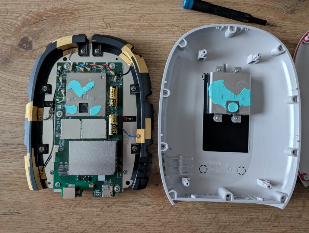
23. The mounting bracket is also a heatsink
One of the most interesting physical findings was that the external mounting structure is part of the cooling system.
Large amounts of blue thermal-interface material connect the shielded components and internal heat spreaders to the metal structure attached to the enclosure.
The heat path appears to be:
Qualcomm and RF components
        │
        ▼
shield cans and heat spreaders
        │
        ▼
thermal-interface material
        │
        ▼
metal frame and external mount
        │
        ▼
outside air
The mount is therefore not only mechanical. It helps remove heat from the modem and RF components.
This matters when reassembling the unit. Poor contact between the thermal material and the metal structure could reduce cooling performance and potentially cause throttling during sustained n78 operation.
24. The final OpenWrt configuration
The practical OpenWrt arrangement is uncomplicated once the VLAN roles are known.
The internet interface uses:
Device: wan.100
Protocol: DHCP client
Firewall zone: wan
A second interface can be created for management:
Device: wan.104
Protocol: DHCP client
Default gateway: disabled
Peer DNS: disabled
This permits access to:
https://192.168.4.1
without allowing the management network to become the default internet route.
The management interface should ideally be restricted to trusted administrator devices rather than exposed to every LAN client.
The final topology is:
                      ┌─────────────────────────┐
                      │ HT mobile network       │
                      └────────────┬────────────┘
                                   │
                         Qualcomm rmnet interfaces
                                   │
          ┌────────────────────────┼────────────────────────┐
          │                        │                        │
       VLAN 100                 VLAN 101/103             VLAN 104
       Internet                 Private services          Management
          │                                                  │
          ▼                                                  ▼
  OpenWrt WAN DHCP                                  https://192.168.4.1
25. What remains unknown
Despite the amount of information exposed by the log collector, several parts remain unresolved.
The exact purpose of VLANs 101 and 103 has not been proven.
The precise role and authorization model of the persistent SSH daemon are still unknown.
The Bluetooth pairing and discovery process used by the technician has not been reproduced with ordinary tools.
The J103/TP160x pad group has not been electrically identified.
There may also be additional backend actions that are implemented in the management daemons but not referenced by the frontend JavaScript.
These unknowns are important. A research article should distinguish between what was demonstrated, what is strongly suggested by the evidence, and what remains speculation.
26. Security observations
The outdoor unit has several reasonable protections:
- its WebUI is HTTPS-only;
- direct SSH is rejected on the customer management path;
- SNMP and UPnP are not exposed;
- session cookies and CGI tokens are required for management actions;
- some static frontend paths reject requests without the expected context;
- provider services are separated into different VLANs and mobile interfaces.
At the same time, several design choices are interesting from a security perspective.
The hidden engineering pages remain in the production firmware and can be loaded through the normal frontend shell.
TR-069 configuration is editable through one of those hidden pages.
The Log Collector exposes detailed system, firewall, process, and configuration information.
The SSH daemon continues running even when the management model describes SSH as disabled.
The Bluetooth daemon also runs continuously, without an exposed customer control for disabling it.
These findings do not automatically mean that the device is remotely exploitable. They do show that the difference between the visible customer interface and the underlying management surface is substantial.
The firmware does not remove most engineering functionality. It largely hides or restricts it.
27. From 90 Mbps to 620 Mbps
The practical result of the investigation was significant.
The connection started at approximately:
90 Mbps
and later reached approximately:
620 Mbps
That result was not produced simply by replacing the Arcadyan with OpenWrt or by discovering VLAN 100. The larger improvement involved a service-side configuration change that I am deliberately not publishing.
Nevertheless, the reverse-engineering work was what made the broader system understandable.
It established:
- which VLAN carried internet;
- which VLAN carried management;
- how to replace the indoor router;
- how to inspect LTE and NR conditions;
- how to access the engineering diagnostics;
- how the mobile interfaces and APNs were structured;
- how persistent configuration was stored;
- which management services continued running after reboot.
The speed result turned the project from an academic teardown into something with a direct practical benefit.
Conclusion
This project began with an outdoor unit that appeared to be little more than an ISP-controlled 5G modem.
The first assumption was that the visible next-hop address would be the management interface. It was not.
The first VLAN that provided DHCP was not the internet service. It was the management plane.
The first JavaScript download did not contain JavaScript. It contained 403 responses.
The hidden HTML paths were not useful as standalone pages. They had to be loaded through the active WebUI shell.
Each of those obstacles revealed another part of the design.
The final picture is a multi-PDN Qualcomm embedded Linux platform that presents several cellular contexts over VLAN-tagged Ethernet.
The key network findings were:
VLAN 100 → customer internet handoff
VLAN 104 → local ODU management
VLAN 101 → unidentified provider/private service
VLAN 103 → unidentified provider/private service
The key WebUI findings were:
Management URL → https://192.168.4.1
Backend → /cgi-bin/gui.cgi
Web server → lighttpd 1.4.61
Hidden pages → RF diagnostics, LTE CA, logging, TR-069
The key system findings were:
Platform → Qualcomm SDX55/SDXPRAIRIE class
Operating system → embedded Linux 4.14
Management → malmanager and mald
SSH → running but firewall-restricted
Bluetooth → bt_uartd running, used for service access to the WebUI
TR-069 → hidden but configurable, disable persists after reboot
LED setting → disable persists after reboot
The technician visit provided an additional real-world detail: Bluetooth gave the technician a path to the normal management interface, but it did not bypass the changed WebUI password. In the workflow observed, Bluetooth was a transport to the WebUI—not an unrestricted administrative backdoor.
The purpose of the persistent SSH service remains unresolved. It may exist for provider diagnostics, factory use, field support, or recovery, but the customer-side management network does not expose it normally.
Finally, the hardware teardown showed that the unit’s metal mounting structure is also part of its cooling system, transferring heat away from the shielded Qualcomm and RF components.
From the customer’s perspective, this is simply an outdoor 5G box.
Internally, it is a complete provider-managed Linux networking platform with multiple service planes, hidden diagnostics, persistent remote-management components, and a much larger management surface than the normal interface suggests.
And, in practical terms, understanding it was worthwhile: the Arcadyan was replaced with OpenWrt, the management and internet networks were mapped, TR-069 was disabled persistently, the LEDs were turned off, detailed radio information became accessible, and the connection increased from approximately 90 Mbps to around 620 Mbps.